Overview
The MGN12 Linear Rails Kit is designed for the Creality Ender 3 3D Printer. It is Intended to replace the stock v-wheel rollers, offering high precision and smooth motion on the Y axis.
- High Positional Accuracy
- CNC Machined Aluminum Brackets
- Steel core GT2 6mm Belt
- Lightweight Modular Y Carriage
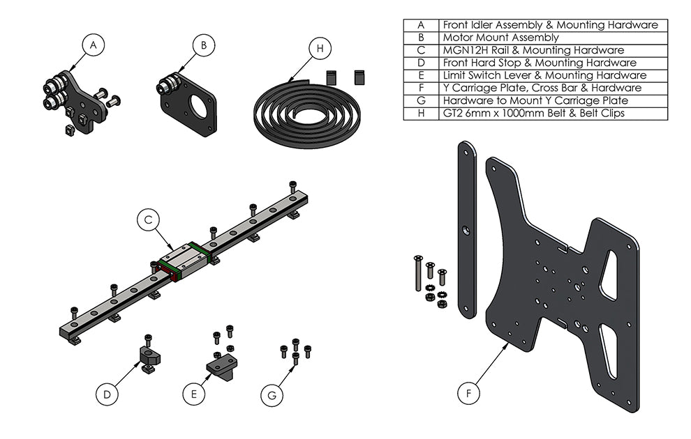
Package Contents
Before Starting
1. Remove Heated Bed
Unscrew and set aside the heated bed and mounting hardware. Take care not to lose the springs during disassembly.
The heated bed will later be re-installed on the new carriage plate using the original hardware.

2. Remove Belt
Loosen the 3x M4 mounting screws on the belt idler (1). Slide the idler back to loosen the belt, then remove clipped belt ends from the carriage slots. Completely remove the stock belt from Y axis assembly.
The original belt will not be reused. It will be replaced with a longer belt included with the MGN12 conversion kit.

3. Remove Belt Tensioner
Unscrew and remove the stock belt idler and T-nuts from the Y axis extrusion. These will not be reused for the MGN conversion.
4. Remove Carriage Plate
Remove the stock carriage assembly by sliding it out of the Y axis extrusion beam. The stock carriage will not be reused for the MGN12 conversion.
V-wheels can be left attached to the stock carriage to prevent small parts from being lost.

5. Remove Motor Mount
Remove stock motor mount (4) by unscrewing 2 x M4x16 screws (3).
Remove stepper motor (1) from stock motor mount (4) by unscrewing 4 x M3x6 screws (2).
The stock motor mount plate (4) will not be used for the MGN12 conversion. It will be replaced with a new motor mount plate.

6. Install Idler Assembly
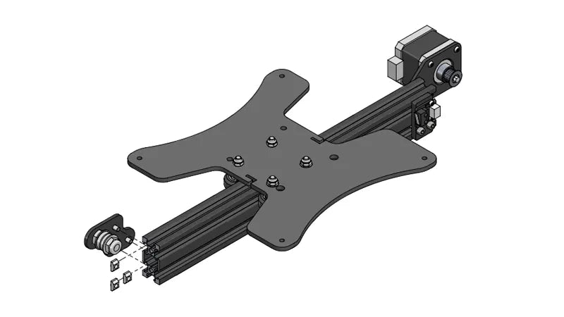
Install the new idler assembly from kit package (A) on the front left of the Y axis as shown. Use the mounting hardware included in package (A).

7. Install Motor Mount
Attach the stepper motor (1) to the new motor mount plate included with the MGN12 kit package (B).
Using the 4 x M3x6 screws (2) saved from stock motor mount disassembly, attach everything to the Y axis extrusion beam with 2 x M4x16 screws (3) also saved from stock motor mount disassembly.

8. Install MGN12 Linear Rail
Install MGN12 rail from package (C) with hardware included in the package (C). Install hard stop from package (D) in front of the MGN12 rail, with included hardware.
When installing MGN12 rail, make sure it is properly centered in relation to Y axis beam extrusion, which means - it is not shifted to the left or right side, and it is parallel to the extrusion.
MGN12 Alignment Block can be 3D printed and used to straighten the linear guide rail and align it to the Y axis extrusion.

9. Install Limit Switch Lever
Attach the limit switch lever from package (E) to the new carriage plate (F). Please note the proper orientation of the lever in relation to the limit switch.

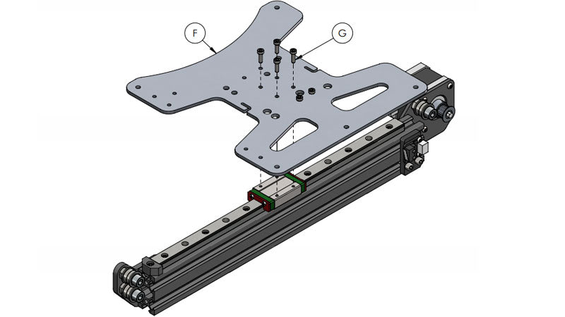
10. Install Y Carriage Plate
Attach new carriage (F) with limit switch lever installed (E) to MGN12H Carriage block using 4 x M3x8 socket head screws. Mounting screws provided in a pckage (G).
Insert (6) M5x8mm socket head screws into the MGN12 linear rail, placing one at each end and then every other hole.
11. Install Belt
Install the new GT2 belt from package (H). Route the belt through the extrusion beam, idler wheels and feed it through the belt slots on the carriage plate. Use the included 3D printed belt clips to secure the belt ends.
The belt in package (H) is longer than required for assembly. Leave 3-4 mm extra length after securing belt with clips and cut off excess.
12a. Install Heated Bed (4 Points)
Mount the heated bed on the Y Carriage Plate using with stock springs and adjustment wheels.

Important! Please Read:
Many Creality 3D Printers come with warped heated beds. This is a well known issue. The heated bed manufacturing process (PCB etching) causes the bottom side of the bed to expand and deviate from flatness.
3-Point bed leveling is an optional modification that will enhance the bed leveling process, but it cannot improve the flatness of the bed. Before converting to 3-Point leveling, carefully check your heated bed's flatness after it has been removed from the 3D Printer. Place a metal ruler across the surface, or lay it on a granite countertop to roughly gauge any deviations in flatness.
If you find that the heated bed is deformed and not flat, you can try manually bending or twisting it back to a flat shape. This procedure is not for everyone, but aluminum is malleable and can sometimes be corrected using this approach. If that does not work, you may need to purchase a new heated bed. We suggest a CNC machined bed with silicone heater to replace the etched PCB aluminum bed. The Ender 3 Heated Bed Kit is available for purchase in our store.
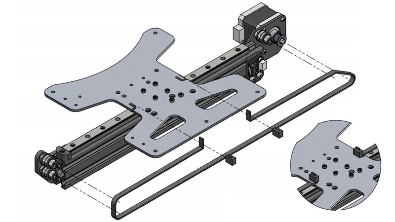
If your Ender 3 heated bed is reasonably flat, and you decided to go with 3-point leveling adjustment for your Y axis MGN12 upgrade - use the cross bar and hardware from package (F) to make the bed modification as it is shown on this drawing.

12b. Install Heated Bed (3 Points)
This is an optional assembly step. Complete it if you decided to use 3-point leveling as described above.

13. Adjust Z Endstop
Locate the Z axis limit switch on the left side of your Ender 3. Loosen the 2x bolts and move the limit switch up 9mm.
